Results 1 to 9 of 9

Thread: My Friday brainfreeze

  1. #1
    Platinum Member Derlyn's Avatar
    Join Date
    Mar 2019
    Location
    East london
    Posts
    1,678
    Thanks
    124
    Thanked 160 Times in 150 Posts

    My Friday brainfreeze

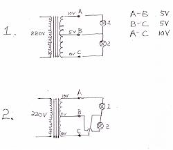
    Looking at circuit No1.

    10V transformer with centre tap at 5V.
    Lamp 1 has 5V across it. Lamp 2 also has 5V across it. Easy peezy.

    Now looking at circuit No2.

    Same transformer with the lamps connected slightly different.
    What voltage would one expect to get across lamp 1 and lamp 2.

    I've hit a blank.

    Click image for larger version. 

Name:	Scan_20220715_152314.jpg 
Views:	337 
Size:	26.2 KB 
ID:	8591

  2. #2
    Platinum Member
    Join Date
    Mar 2022
    Location
    South Africa
    Posts
    2,274
    Thanks
    60
    Thanked 103 Times in 98 Posts
    That is what is referred to as an auto transformer. You would connect the lights as per figure 2

    0V is the ground reference

    A-C -= 10 V

    B-C = 5 V

    We have them on the control circuits for the machines (because it is cheaper).

    Normally 400 V - 230/110/24 V

  3. #3
    Platinum Member Derlyn's Avatar
    Join Date
    Mar 2019
    Location
    East london
    Posts
    1,678
    Thanks
    124
    Thanked 160 Times in 150 Posts
    What I am finding difficult to understand is that if you have 10V across lamp 1 (A-C ) and 5V across lamp 2 (B-C) then because series voltages are added, you should get 15V across both lamps (A-B) but the transformer is only 10 Volts.

  4. #4
    Platinum Member Derlyn's Avatar
    Join Date
    Mar 2019
    Location
    East london
    Posts
    1,678
    Thanks
    124
    Thanked 160 Times in 150 Posts
    Ok. Problem solved.

    Not really a problem.
    Just a complicated way of drawing a simple circuit.

    I have redrawn circuit 2 simpler and found the lamps not to be in series.

    Sorry guys. This is NTC 1 stuff but sometimes one hits a blank.

    Have a lekker weekend.


    Click image for larger version. 

Name:	Scan_20220716_091001.jpg 
Views:	350 
Size:	23.2 KB 
ID:	8592

  5. #5
    Diamond Member Justloadit's Avatar
    Join Date
    Nov 2010
    Location
    Johannesburg
    Posts
    3,505
    Thanks
    138
    Thanked 697 Times in 595 Posts
    Blog Entries
    1
    Just to add into the mix here, what if the winding A-B was inverted, in other words when the transformer was wound, they used 2 secondaries, and then made a connection for the centre?

    Would you measure 5V between A-B and B-C?
    Now what would the voltage be between A-C - 10V or 0V?
    Victor - Knowledge is a blessing or a curse, your current circumstances make you decide!
    Solar pumping, Solar Geyser & Solar Security lighting solutions - www.microsolve.co.za

  6. #6
    Platinum Member
    Join Date
    Mar 2022
    Location
    South Africa
    Posts
    2,274
    Thanks
    60
    Thanked 103 Times in 98 Posts
    Quote Originally Posted by Justloadit View Post
    Just to add into the mix here, what if the winding A-B was inverted, in other words when the transformer was wound, they used 2 secondaries, and then made a connection for the centre?

    Would you measure 5V between A-B and B-C?

    Now what would the voltage be between A-C - 10V or 0V?
    Then you would have a V-O-V transformer and it would apply the same as the generators.

    110V - 0V - 110V (A - B - C)

    A-C would be 220V

  7. #7
    Diamond Member Justloadit's Avatar
    Join Date
    Nov 2010
    Location
    Johannesburg
    Posts
    3,505
    Thanks
    138
    Thanked 697 Times in 595 Posts
    Blog Entries
    1
    Quote Originally Posted by Derlyn View Post

    Click image for larger version. 

Name:	Scan_20220715_152314.jpg 
Views:	337 
Size:	26.2 KB 
ID:	8591
    Quote Originally Posted by Isetech View Post
    Then you would have a V-O-V transformer and it would apply the same as the generators.

    110V - 0V - 110V (A - B - C)

    A-C would be 220V
    The above picture marked as #1 is a V - 0 - V
    It has all to do with the phase of the voltages being measured.
    A - is the start of the winding, and ends at B
    B - is the start of the second winding, and ends at C.
    When the AC wave goes positive, it is in phase in both windings simultaneously, and you will measure the 10V between A and C

    The scenario I refer to, is that the first winding starts at A, and ends at B
    The second winding starts at C and ends at B.
    So when the AC wave goes positive in the A-B winding, the wave goes negative in the B-C so when you measure from A to C, you will measure 0V.

    Sometimes when a transformer has 2 secondary windings, and we wish to double up on the current, then it is very important to identify the start of each winding when you connect them in parallel, if not then you would be shorting the transformer out.
    Victor - Knowledge is a blessing or a curse, your current circumstances make you decide!
    Solar pumping, Solar Geyser & Solar Security lighting solutions - www.microsolve.co.za

  8. #8
    Platinum Member Derlyn's Avatar
    Join Date
    Mar 2019
    Location
    East london
    Posts
    1,678
    Thanks
    124
    Thanked 160 Times in 150 Posts
    @justloadit. Yep. That was a test that the tutor loved giving us as appies.

    We used a battery and an analogue voltmeter. You would flick on the primary with the battery and check which way the needle deflected on the voltmeter connected on the secondary.

    Same test used on 3 phase motors to check the 3 windings for phasing.

    Interesting stuff.

  9. #9
    Platinum Member
    Join Date
    Mar 2022
    Location
    South Africa
    Posts
    2,274
    Thanks
    60
    Thanked 103 Times in 98 Posts
    That why it is important to understand if it is a double would or an auto transformer.

    A 3 phase motor for example can in some cases can be used as a 230 or 400 V 3 phase motor depending on the bridge pieces (star or delta)

    That is why it is so important to read the name plate and data sheet.

Did you like this article? Share it with your favourite social network.

Did you like this article? Share it with your favourite social network.

Posting Permissions

  • You may not post new threads
  • You may not post replies
  • You may not post attachments
  • You may not edit your posts
  •