Page 15 of 25 FirstFirst ... 51314151617 ... LastLast
Results 141 to 150 of 242

Thread: Saturday at home, installing an inverter

  1. #141
    Diamond Member tec0's Avatar
    Join Date
    Jun 2009
    Location
    South Africa
    Posts
    4,624
    Thanks
    1,884
    Thanked 463 Times in 410 Posts
    Blog Entries
    3
    Quote Originally Posted by daveob View Post
    Look at the Mega2560 instead. Has 54 I/O pins instead, and not that much more cost.

    Personally I use a Mega2560 for home automation ( 3 x gate control, alarm system, sms to cell on trigger, web based control of gates, alarm, smart sensor control ( eg disable indoor passives in living room area when kids break beams in passageway in the morning, etc ).

    Yes, you will find a lot of open source code based on Arduino for charge controllers, etc.

    Just remember that boards like the Arduino have a 'per pin' and 'total board' current limit, so outputs are basically limited to an LED or an NPN transistor ( which in turn can drive much bigger loads ).

    Once you have an Arduino, you can also use it to program a stand-alone atmega IC ( about R70 for atmega vs R350 for Uno ) so once your code is working, push it on to an atmega and reduce your hardware cost.

    ps .. when you make a board for the atmega IC, use an IC saddle ( type of socket that the IC clips into ). If you have a system problem, very easy to remove the IC brains and replace it with the spare that you made.
    Yes you are right on every aspect... I am just lazy

    yes it is expensive and yes Arduino is limited. What I like about it is the ecosystem it plugs into. The Arduino Mega R3 for example is a really nice board. Also i like to use the 4 Channel Relay Board For Arduino and it just works actually... Never had problem with it You can always adapt to a solid-state relay if you need to or even go to heavy-duty contactor using relay logic... It is a bit old school but it gets the job done.
    peace is a state of mind
    Disclaimer: everything written by me can be considered as fictional.

  2. #142
    Email problem IMHO's Avatar
    Join Date
    Jan 2012
    Location
    NW
    Posts
    540
    Thanks
    11
    Thanked 54 Times in 48 Posts
    daveob, I would love to identify the charger circuit and hack it to float charge to 26 volt , or disable it all together. The problem is I am not an electronic boffin and do not know how to. I can Google and YouTube, but not knowing where the charging circuit is, stp me in my tracks. Can you help?


    ~Expenses will eat you alive! - My first Boss~

  3. #143
    Email problem IMHO's Avatar
    Join Date
    Jan 2012
    Location
    NW
    Posts
    540
    Thanks
    11
    Thanked 54 Times in 48 Posts


    ~Expenses will eat you alive! - My first Boss~

  4. #144
    Email problem daveob's Avatar
    Join Date
    Feb 2008
    Location
    Amanzimtoti
    Posts
    655
    Thanks
    107
    Thanked 118 Times in 103 Posts
    Quote Originally Posted by IMHO View Post
    daveob, I would love to identify the charger circuit and hack it to float charge to 26 volt , or disable it all together. The problem is I am not an electronic boffin and do not know how to. I can Google and YouTube, but not knowing where the charging circuit is, stp me in my tracks. Can you help?
    Hi IMHO

    Sorry, but I have to be able to admit that what you are asking is not my area of expertise, so I would not want to give you incorrect info or advice, knowing full well that it could lead to disaster.

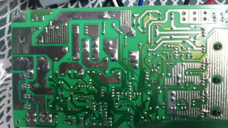
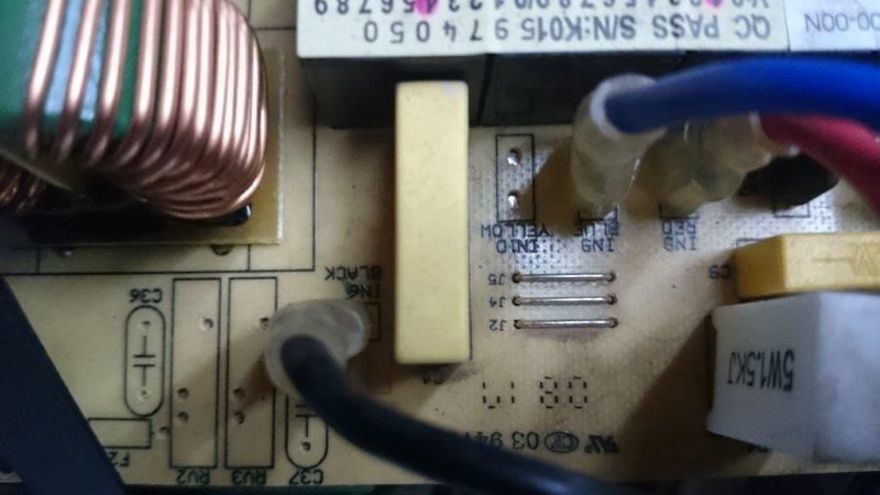
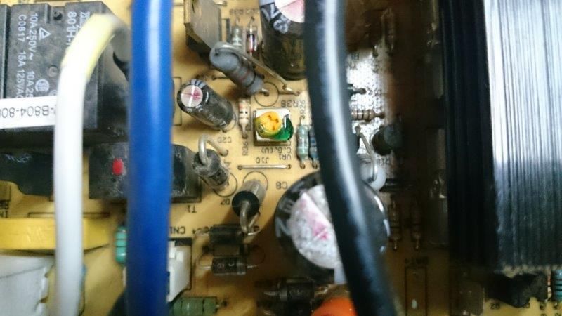
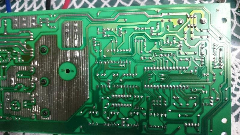
    I can tell you a little about the pics you posted from what I can see. WARNING : this is all what I think I see. I have NO formal training or qualifications in this field :

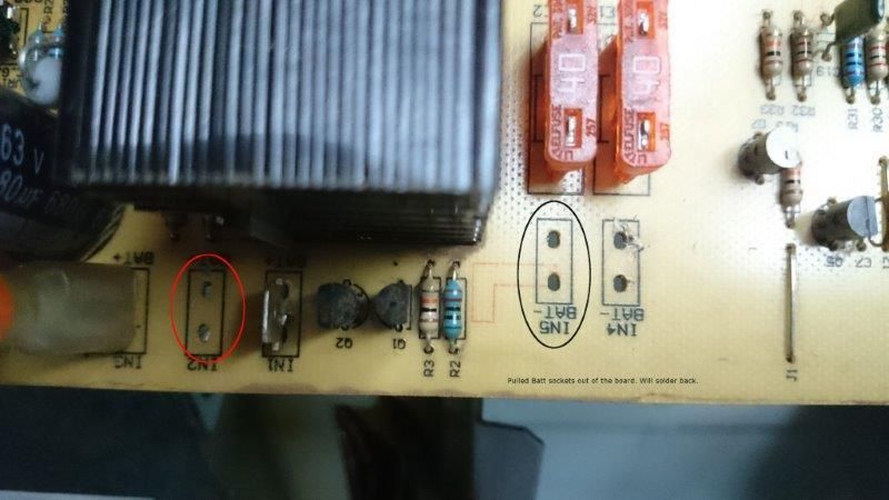
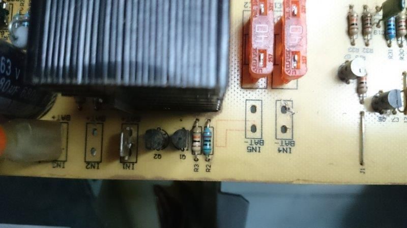
    pic 1 : a lot of these boards are designed as generic / multi purpose boards, so you will find a few holes on the pcb with diagrams printed on them for parts that are not populated. Those would be for a different model.

    pic 2 : see the round black cylindrical thingy with the 63v printed on the side ? WARNING WARNING WARNING WARNING - those have big teeth. It is a capacitor that is designed to store energy. They are used to absorb fluctuations in the current flowing through them, making your ups run smoother and 'cleaner'. They are also designed to discharge that same energy - and can do so VERY fast. And even if your board is disconnected from the mains, they still retain their energy. If you touch the contacts on a capacitor, or short them together, there will be a shock, or a lot of sparks. One of the main reasons why warning signs are posted on things telling you not to open them. Ask me, I know. Was working on modifying a disposable camera flash bulb for a swim timing system a while back, and accidentally touched a 300V capacitor. After the feeling returned, my arm was still tingling for a few days.

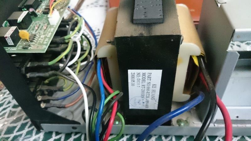
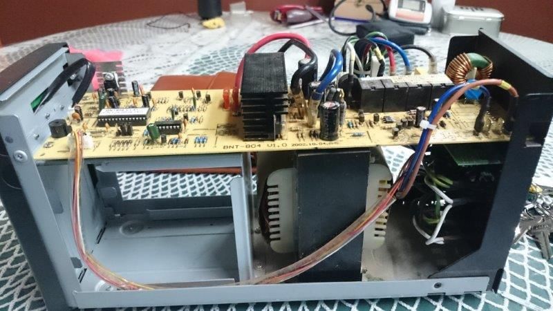
    pic 3 : that huge thing is, I suspect, a step up transformer. Most likely takes 24VDC input ( higher current = thicker wires ) and outputs 220VAC ( lower current = thinner wires ).

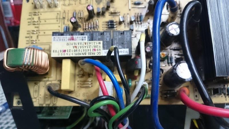
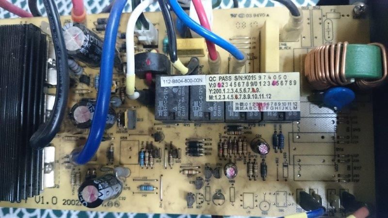
    pic 4 : the 4 black cubes in the middle are relays. From what I can see, most likely magnetic coil switching relays.

    Assuming the big transformer is a step up, the relays likely cause the 24VDC from the battery to be connected to the step up transformer when the mains fails.

    The round black component with the red wire through it, at the bottom right of the relays, is a current sensor. That would detect when the mains has failed, and would cause the relays to kick in.

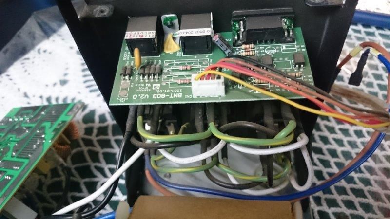
    pic 9 : the board mounted to the back of the case contains the rs232 comms plug, and the phone in / out plugs for surge protecting of the phone line. The 5 cable plug connects the comms board in the pic to the charge pcb. That comms board would have no effect on the charging of the batteries.

    Pic 9 also looks like the mains in to the UPS are connected directly to the output sockets on the UPS. That means the mains, when present, will flow directly from the input to the output. Only when the mains fails, will the pcb connect the battery to the transformer and output 220V to the output sockets.

    pic 10 : the notably thicker wires are probably the wires from the battery to the board, and / or from the board to the transformer. They are thicker so that they can carry more current. ( ignoring AC and DC for now, 1A @ 220V would be 220Watts, but 220W @ 24V = 9 amps. Amps = current, so higher current needs thicker wires.
    Same logic is used for solar PV panels. Connect in series to increase voltage = lower current = thinner wiring needed from panels to charge controller.

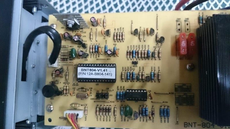
    pic 11 : shows an IC ( chip ). This is most likely something like an atmega or pic chip that is programmed with the 'logic' for the board and controls what it does.
    The item at the top left that is bolted to the silver heat sink would be either a FET or a voltage regulator. There are some small capacitors close by ( the light brown 'blob' components ) and these are typically used to smooth the output of the voltage regulator. It should have numbers printed in the voltage reg. something like 7805 ( the '05' indicates that it supplies 5VDC output ) and would be used to regulate the voltage that the IC chip needs to run.
    The round black component at the bottom left with the hole in the top is a piezo buzzer. Very low current but very noisy and irritating beeper when the UPS is running. I dropped a spot of pratleys quickset on the top of mine and it is a lot quieter.

    Sorry, but I know this does not really help you one bit, but hope it does give you some idea of what those components are.

    If you really want to do mods to this board, you may want to look at some of the electronics forums, of put a job up on fiverr ( $5 ) for someone to source you a wiring diagram / schematic and to tell you what to modify.
    Watching the ships passing by.

  5. #145
    Diamond Member AndyD's Avatar
    Join Date
    Jan 2010
    Location
    Cape Town
    Posts
    4,924
    Thanks
    576
    Thanked 934 Times in 755 Posts
    Quote Originally Posted by daveob View Post
    Actually, having just thought about that, I think it also important to point out that in so many cases, people are spending small fortunes on systems to ensure that they have power when the outage hits - but little or no thought or concern about what happens when the power is restored.

    There have been numerous mentions of routers that work erratically. The mains power is all over the place when it comes back on and everyone starts up at the same time. So if you're getting 180VAC into the router transformer that expects 200 - 240VAC, then the 12VDC output may not be 12V and the router starts doing weird things.

    Or the TV set and sound system that you paid +R12k for that is subject to wild voltage swings on power up.

    Or this pride & joy battery system. What happens when the power comes back on. Does the UPS immediately disconnect the battery and router the mains to the devices plugged into the UPS ? Most likely the case. What effect does voltage changes have on the charging circuit ?

    The solution is to install a device that can :
    1. prevent the mains power from being supplied down the line.
    2. monitor the incoming mains voltage until it is above a set value ( eg. 200VAC ) and below 240VAC.
    3. Start a timer ( eg 5 minutes, 15 min, etc )
    4. delay the supply of mains power downline until the timer has expired ( unless the override button is pressed )

    That way, you get to minimise the startup impact on your equipment.
    I did make a thread about this a while ago because it's something that's often not taken into consideration at the design stage of a back-up system and it affects the entire spec including the battery requirements and the selaction of appropriate inverters etc.

    Another solution to add to the 4 you mentioned is to replace the power supplies on any devices such as routers, alarms, PABX's etc if the original has a tight band of voltage requirement. I did this with my Netgear router, the original power supply plug was the heavy transformer type and was rated for operation between 220-240 volts, I purchased an equivalent switch mode type supply with a wider voltage band of 100-250 volts and it solved a lot of random conectivity and networking problems I was having.
    _______________________________________________

    _______________________________________________

  6. #146
    Diamond Member tec0's Avatar
    Join Date
    Jun 2009
    Location
    South Africa
    Posts
    4,624
    Thanks
    1,884
    Thanked 463 Times in 410 Posts
    Blog Entries
    3
    Ok what inverter to use, i am told that some inverters can actually damage the refrigerator? I am asking this because I am getting into contact with a supplier that sells a 9000 Watt system for R36k That is not bad because it is a complete working system. Thing is I don't know the makes and parts so in the end I am stepping on a real risk of getting shot in the foot...

    Questions I will be asking.
    How strong are the Solar panels?
    Can the inverter be used on electronics like TV, DVD player, PC Refrigerator and Freezer?
    How long will everything last under load?
    Can the batteries be charged from a second source "like generator"?

    Please add your question here...
    peace is a state of mind
    Disclaimer: everything written by me can be considered as fictional.

  7. #147
    Email problem daveob's Avatar
    Join Date
    Feb 2008
    Location
    Amanzimtoti
    Posts
    655
    Thanks
    107
    Thanked 118 Times in 103 Posts
    Quote Originally Posted by AndyD View Post
    I did make a thread about this a while ago because it's something that's often not taken into consideration at the design stage of a back-up system and it affects the entire spec including the battery requirements and the selaction of appropriate inverters etc.

    Another solution to add to the 4 you mentioned is to replace the power supplies on any devices such as routers, alarms, PABX's etc if the original has a tight band of voltage requirement. I did this with my Netgear router, the original power supply plug was the heavy transformer type and was rated for operation between 220-240 volts, I purchased an equivalent switch mode type supply with a wider voltage band of 100-250 volts and it solved a lot of random conectivity and networking problems I was having.
    Hi AndyD

    I recall that thread. Although I agree with your solution and how the problem was solved, my first concern would be the fact that this 'proves' that the mains supply after an outage is most certainly not clean or stable. I have a basic home entertainment system - nothing fancy - TV, DVD, sound, PVR, VHS ( yes, VHS ), TV games, etc, but combined it probably easily costs in excess of R20K.

    So while the R600 router is now working ( working = operational, not protected from accelerated electronics wear and tear ), the R20K entertainment system is still subject to 'severe electrical abuse'.

    This is partly why I started working on my solution. The prototype is done and working, and I am now waiting for PC Boards to be produced.

    Essentially the "Mains Delay" unit will block mains power to the EC ( entertainment center ) until the mains voltage is consistently in the 210 - 240V range, and then the "Mains Delay" unit has an internal timer to wait a preset number of minutes ( eg 5, 10, 15 minutes ).
    Only after the timer has run, will the mains be switched on to the EC.

    The minimum voltage spec, as well as the number of minutes to wait, is set by the user with the buttons on the side of the "Mains Delay" unit.

    Another very good use for this is on power tools and industrial equipment.

    Saw another post ( might have been part of your original post ) about a power tool having been left on at the start of outage, and serious hazard when power comes back on. Am thinking grinders, drills, soldering irons, etc.

    Simply install this unit at the plug point, set the 'time delay' to '0', and once the power is restored it will block the mains power to the equipment until the user presses the button on the unit.

    That was originally added to the design because I was tired or the missus complaining ( twice !! ) that all the PVR auto-tune and recording settings were lost when the PVR rebooted, unless you 'cancel' the Scan during the PVR bootup.

    Another perfect place for this is on the supply to my UPS.

    UPS is great when the mains fails, but on restore, the batteries are 'switched off' and mains supply, no matter how dirty and nasty, is sent directly to my PC. Had 2 PCs in the last 18 months that popped when power came back on.

    Bottom line is, as you say, put some serious thought into protecting your equipment. Not just when the power dies, but more importantly what it is subject to when the mains returns.
    Watching the ships passing by.

  8. #148
    Email problem daveob's Avatar
    Join Date
    Feb 2008
    Location
    Amanzimtoti
    Posts
    655
    Thanks
    107
    Thanked 118 Times in 103 Posts
    Quote Originally Posted by tec0 View Post
    Ok what inverter to use, i am told that some inverters can actually damage the refrigerator? I am asking this because I am getting into contact with a supplier that sells a 9000 Watt system for R36k That is not bad because it is a complete working system. Thing is I don't know the makes and parts so in the end I am stepping on a real risk of getting shot in the foot...

    Questions I will be asking.
    How strong are the Solar panels?
    Can the inverter be used on electronics like TV, DVD player, PC Refrigerator and Freezer?
    How long will everything last under load?
    Can the batteries be charged from a second source "like generator"?

    Please add your question here...
    Hi tec0

    I would be looking at info like :
    1. what voltage are the panels ?
    2. configuration : Series or Parallel.
    3. what size wire is needed from panels to charge controller.
    4. what are the battery specs.
    5. what is the efficiency rating of the inverter ?
    6. what is the normal and max output of the inverter ?
    7. how many batteries, and series or parallel ?
    8. Cooling
    9. Ventilation
    10. can the controller also accept input from a wind turbine ?
    11. where does it dump power when batteries are charged ? Can this be connected to a water heater / pool heater element ?
    12. what is the battery charging schema ? what is the max voltage / amp sent to the battery. when does it step down as the battery approaches fully charged and at what values, how does it maintain charge ?

    As a general run of thumb, you can work on the following :

    assuming 2 x 12V 105aH deep cell batteries, connected in series.
    So you get a 24V x 105aH power source.
    24V x 105aH = 2520 watts of power. But that is from fully charged to absolutely completely dead - dead as in destroyed )
    So you get the battery specs, and find the absolute maximum discharge limit.
    Remember that hitting that max limit will mean the life span of the batteries is seriously reduced.
    So maybe you decide to work with a 50% discharge limit.
    So 2520 watts x 50% = 1260 watts ( usable battery power ).
    Next it has to pass through the inverter.
    Cheaper inverter = less efficient.
    Lets say it is average quality, and eff. is 75% ( so you lose 25% of the energy in the inverter conversion )
    1260 watts x 75% = 945 watts. btw, that other 25% does go somewhere - heat from the inverter = ventilation requirements.

    So you can look at the specs on your appliances and work out just how long you can run things for with that amount of power.

    Personally, I would not run anything with a motor from an inverter ( unless it is a true pure sine wave inverter, but thats $$$$$s ) . It is not good for the motor. AndyD would likely be able to better explain why.
    Also I would not connect anything that is power hungry, has an element of any kind, etc.

    A lot of the suitability of this system is going to depend very heavily on the batteries. Their replacement cost is a huge chunk of the cost of the system. Make sure you know everything about those batteries, discharge rates, limits, etc before you part with your cash.

    Get an independant price for the replacement of the batteries, and factor this into your 'total cost or ownership' as they will need replacing. How often ? depends on usage and abuse. I would probably estimate around 5 years. Sounds long, but if you have 4 batteries x R1500 each = R6000 = average R 1200 per year additional cost. Battery specs will say a life span of something like 10 years. Yes, 10 years - in IDEAL situations, perfect charging schema, minimum discharge rates, etc. This is the real world - half their number.

    In case you didn't know, batteries have different life expectancy based on rate of discharge.
    Pull that 1260 watts from the battery in 10 minutes every day, and the battery might last 1 year.
    Pull same 1260 watts from the battery over 2 hours every day, and it may last 10 years.

    Look carefully at the specs.

    2c


    ps .. you mentioned 9000w

    Is that 9000w total battery X 50% discharge limit X 75% inverter efficiency = USABLE 3375 watts ? Big difference.

    9000 w would be around 8 batteries ( 8 batteries x 12v = 96V x 100aH = 9600W x 50% x 75% = 3600 usable )

    If it is 9000w usable, it would need :
    9000 usable = 9000 / 75% / 50% = 24000W / 100aH / 12V = 20 batteries.

    Replacement cost =
    8 x R 1500 = R 12000
    or
    20 x R 1500 = R 30000

    Based on just the replacement cost of the batteries, it is highly unlikely that the system you are looking at for R36K, including panels, charger, etc, contains 20 deep celll batteries.

    Chances are it has 6 or 8 batteries, making the usable watts around 3600W - a lot less than the 9000 watts.

    Ask lots of questions without letting on that you know what you know. If the answers you get are not adding up to what you know, then chances are everything you're being told is 'subject to exageration'.
    Watching the ships passing by.

  9. #149
    Email problem IMHO's Avatar
    Join Date
    Jan 2012
    Location
    NW
    Posts
    540
    Thanks
    11
    Thanked 54 Times in 48 Posts
    Quote Originally Posted by daveob View Post

    Another perfect place for this is on the supply to my UPS.

    UPS is great when the mains fails, but on restore, the batteries are 'switched off' and mains supply, no matter how dirty and nasty, is sent directly to my PC. Had 2 PCs in the last 18 months that popped when power came back on.
    .
    Excellent . I lost 4 power supplies to my PABX and eventually the R40K PABX as well.

    Edit: From behind a UPS.

    PPS: Maybe the fact that the UPS's batteries was shot and switched on and off the whole time when the AC fail had something to do with it...
    ;-)
    ~Expenses will eat you alive! - My first Boss~

  10. #150
    Email problem IMHO's Avatar
    Join Date
    Jan 2012
    Location
    NW
    Posts
    540
    Thanks
    11
    Thanked 54 Times in 48 Posts
    daveob, i did n fiverr request, thanks for the tip. Did not know about the fiverr concept.
    ~Expenses will eat you alive! - My first Boss~

Page 15 of 25 FirstFirst ... 51314151617 ... LastLast

Similar Threads

  1. [Question] Installing new electrical outlets in my home
    By julies in forum Electrical Contracting Industry Forum
    Replies: 6
    Last Post: 26-Aug-14, 06:22 AM
  2. Was Saturday 11th's Important Announcement a bad PR exercise?
    By gac in forum South African Politics Forum
    Replies: 4
    Last Post: 13-Feb-12, 01:37 PM
  3. Installing Pastel express V.11 on Laptop.
    By Vinruby in forum Accounting Forum
    Replies: 1
    Last Post: 07-Dec-11, 02:52 PM
  4. Installing Windows XP on VB
    By Faan in forum Technology Forum
    Replies: 7
    Last Post: 17-Jun-11, 07:18 PM
  5. Battery + inverter advice required
    By daveob in forum Electrical Load Shedding Forum
    Replies: 12
    Last Post: 24-May-08, 04:05 PM

Did you like this article? Share it with your favourite social network.

Did you like this article? Share it with your favourite social network.

Posting Permissions

  • You may not post new threads
  • You may not post replies
  • You may not post attachments
  • You may not edit your posts
  •